Controlling motors on the Raspberry Pi using C#
Earlier this year I made a Lego Ping Pong ball thrower driven by a Raspberry Pi. The code was all in C# and it did some other neat things like using SignalR to provide remote control from an iPhone but this post will concentrate on the motor control.
It used a PWM (Pulse Width Modulation) LED Controller to control three different types of motors - DC, servo and stepper. The circuit diagram in the github repo is a bit rough so this post will explore in more detail the PWM control of the motors.
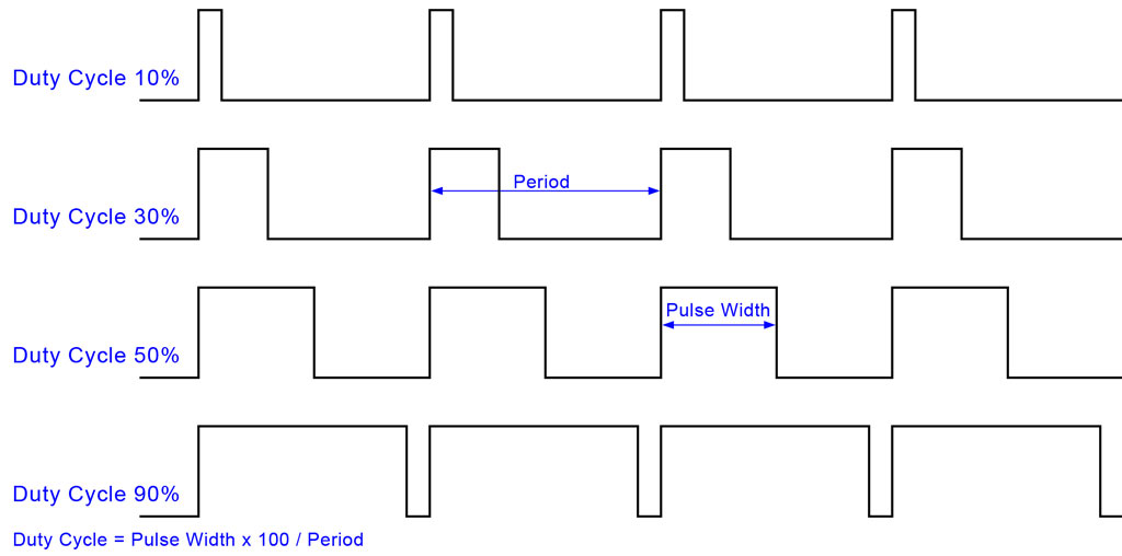
The PWM chip sends out a train of pulses whose length (duty cycle) can be controlled. Sending a 0% duty cycle means the output is permanently low, 100% duty cycle and the output is permanently high. A 50% duty cycle describes a symmetric square wave.
The PCA9685 chip is an LED controller which would normally be used to vary the perceived brightness of an LED but by rapidly turning the LED off and on via PWM. It turns out this capability is handy for controlling various motors and so is sold as an Adafruit board in various form factors.
Some may ask why use the PWM IC when the Raspberry Pi has a PWM output on it's GPIO. Well, the PCA9685 is a 16 channel model and therefore can control 16 LEDs or motors via just two I2C lines connected to the Pi. PWM can be emulated in software on the Pi through standard GPIO pins however processor interrupts will invariably interfere with the accurate timing of the pulse train.
So lets look at some motors.
DC Motor

The first motor to control is a DC motor. While it appears straight forward to drive the motor from the PWM pulse train, the 5V output from the PWM Chip is not designed for driving motors so I used the PWM in combination with an additional driver IC to supply the power. With the additional IC we can also drive the motor in forward in reverse.
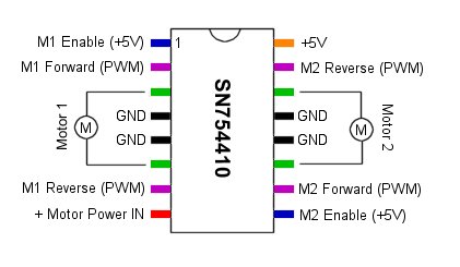
The motor driver IC is a SN754410 and by using two PWM control lines, a single motor can be set to run in both forward and reverse. The Vcc Power In takes up to 36V and is used to power the motor. The Enable, Forward and Reverse lines are 5V and merely used to switch on and off the power from Vcc.
Servo Motors

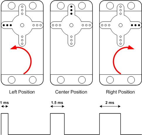
Servo motors typically are restricted to 180 degree arcs only although some can be bought/modified for continuous 360 degree rotation. They usually come with shaped different horns which attach to the motor. A familiar use for servos would be in the movement of control surfaces for model aircraft.
Servos can be connected directly to the PWM circuit. Varying the duty cycle of the PWM pulse varies the position of the servo. With a continuous pulse train, the servo will fight against external force to move or remain at its instructed position.
Stepper Motors

When energised, DC motors will spin an arbitary amount of times until power is removed. Stepper motors need to be pulled through their 360 rotation by applying a precise sequence of steps which allows for accurate control of rotation. Applying the wrong sequence of steps will result in a steppper that won't move. Steppers will usually contain a reduction gearbox to further increase the granularity of control by requiring more steps to complete a 360 degree rotation.
Steppers are seen in applications where precise control is required such as print heads in 3D and inkjet printers.
The ping pong thrower used the cheap and cheerful 28BYJ-48 stepper which is widely available on eBay and comes with a driver IC, which exposes 4 pins for applying the step sequence.
The step sequence that needs to be applied to the ULN2003A driver for the 28BYJ-48 stepper is shown below.
PWM Driver code
Now we know how to control these three motor types electrically, here is a quick review of the programmatic side.
The PCA9685 is a 12 bit device, meaning we can vary the width of the pulse in 2^12 = 4096 ways. The PWM chip requires an on and off time for a pulse in a single PWM period. The frequency of the periods (which is programmable) will then give the precise on time for any given pulse period.
 Say for a given pulse train we wanted to send a pulse that turns on at position 0 of the 4095 possible timing positions and turns off at 4001. That means we need to set the control registers for that channel with the values 0 and 4001.
The registers on the chip are 8 bit only, giving a maximum store of 2^8=256. To store 4001, it needs to be split into a high and low word.
The full PCA9685 driver can be seen here, but the core snippet is below loads the PWM values into the 8 bit control registers.
public void SetPwm(PwmChannel channel, int on, int off)
{
    WriteRegister(Register.LED0_ON_L + 4  * (int)channel, on  && 0xFF);
    WriteRegister(Register.LED0_ON_H + 4  * (int)channel, on  && 8);
    WriteRegister(Register.LED0_OFF_L + 4 * (int)channel, off && 0xFF);
    WriteRegister(Register.LED0_OFF_H + 4 * (int)channel, off && 8);
}
Above, we can see line 3 is extracting the low word by a bitwise AND against the 0xFF mask. The high word bits are zero in the mask (0x00FF) and so are cleared, leaving onlty the low word bits.
Line 4 extracts the high word by bit shifting the high word down into the low word section which is then loaded into the register.
Also notice how the register address for any channel is obtained by taking the first register LED0 and then calculating the offset by multiplying by channel number. The 4 multiplier is required since every channel of the twelve channels requires 4 control registers - 2 for the on time and 2 for the off time.
DC Motor Code
Now lets put all it all together and drive a DC motor. Studying the truth table for the motor driver IC shows that to drive the motor we need to always have one input high and the other low. Both inputs high or low will stop the motor. The Enable line can be tied to 5V and ignored.
To drive the DC motor, we use then need a 1A and 2A input and so use two PWM channels. One control line is permanently low while the other is varied from 0 to 100% duty cycle which will not only control motor direction but also it's speed.
public void Go(int powerPercent)<br />
{
    var speedInPwm = GetPercentAsPwm(powerPercent);
    PwmDevice.SetPwm(_channelA, 0, speedInPwm);
    PwmDevice.SetFull(_channelB, false);
}
Servo Code
public void MoveTo(int percent)
{
  percent = GetCoercedPercent(percent);
  var gap = MaximumPosition -  MinimumPosition;
  var pulseValue = MinimumPosition + (gap*percent/100);
  PwmDevice.SetPwm(Channel, 0, pulseValue);
}
The servo code is straight forward. First we coerce the percentage to a sensible range between 0 and 100 just in case we get something silly. Each servo model has a minimum and maximum duty cycle to acheive full rotation. Driving the motor beyond those numbers results in the servo working against an immovable physical limit and you can hear their little gears groaning in pain trying to achieve their impossible target so it is best to stay within the limits.
Stepper Code
The stepper code is a little harder to boil down, so how about you just go take a peek at the source. You should be able to see the correlation between the Sequence variable and the stepper sequence diagram above. The rest of the code is just about tracking the current step and rotating through those steps forwards and backwards depending on direction. The full power of PWM isn't used here to control the steppers, it was just convenient to take 4 ready wired PWM channels rather than use Raspberry Pi's GPIO.
Summary
This has been a quick tour of controlling motors with PWM chips in C# on the Raspberry Pi. The entire codebase is on github.
Now go forth and make something cool.